3D Model to a Metal 3D Printed part using the Markforged System
The Markforged Metal X 3D print system is the next major revolution in 3D printing. It’s a manufacturing solution that covers the full production process from start to finish. This blog takes a closer look at the step-by-step process of the whole Metal X system.
Main Points Covered:
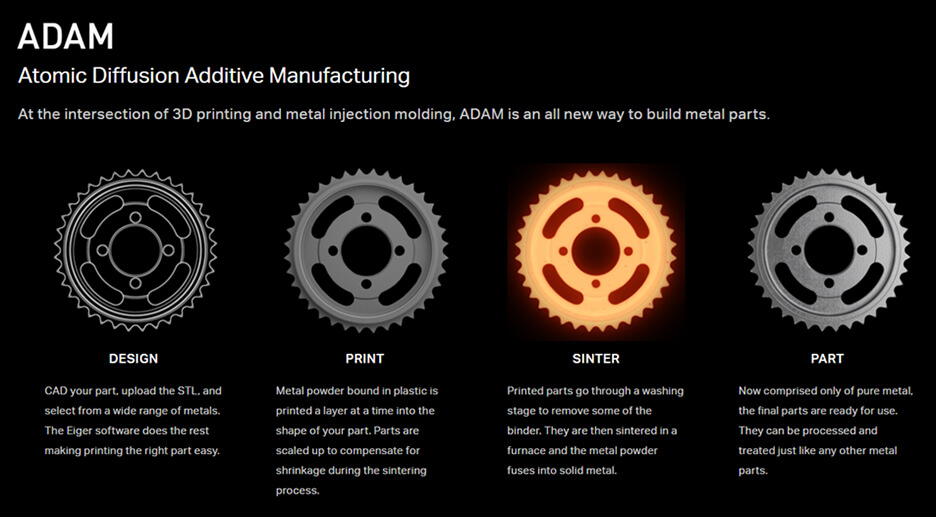
ADAM Overview
ADAM (Atomic Diffused Additive Manufacturing), a hybrid of metal injection moulding and 3D Printing, is a technology used by Markforged to produce metal parts. In the CAD software, a 3D model of a part is designed which is then exported to a STL file. The STL file is brought into Markforged’s software ‘Eiger’ and is sent to the printer. The printer creates the part using a material that is a combination of a metal powder and a binder (plastic). The binder is what allows the metal powder to stay in place as it travels through the post processing system. The post processing is there to remove the binder and allow the metal powder to densify. When completed, the result is a solid and functional metal part.
ADAM Overview: Part Scaling
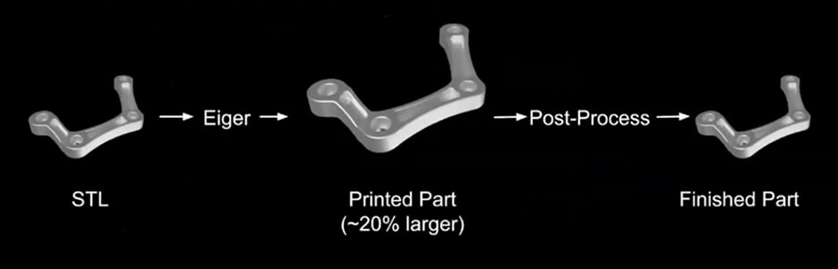
While the size of the part designed in the CAD software doesn’t change when exported to the STL file, the scale automatically increases by approximately 20% when imported into Eiger. This is to compensate for the shrinkage of the part that occurs during the sintering processing. The finished part at the end of the ADAM process is the correct size as per the original CAD design.
Printing: Printer Settings
Material:
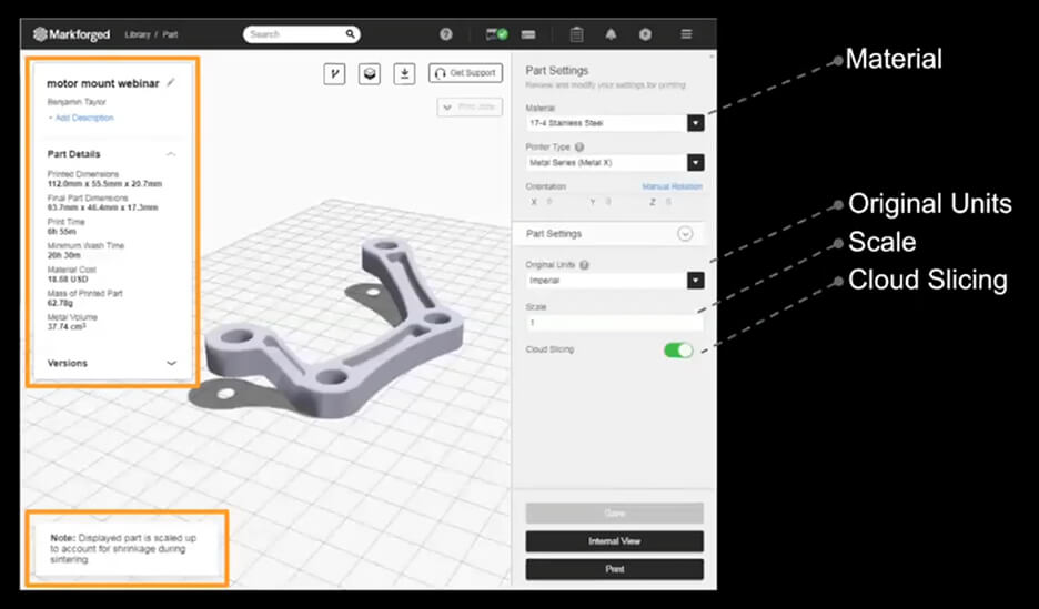
Below is a look at the printer settings that are available in Eiger. By selecting a type of metal from the materials drop down, Eiger is notified that the metal system needs to be used. This then shows metal printing options in the Part Settings.
Original Units:
The first option is the Original Units which just needs to match whatever you exported the file from CAD – this can either be imperial or metric units.
Scale:
Next is the scale and on the bottom left corner, a notification is shown saying ‘displayed part is scaled up to account for shrinkage during sintering’. To further scale the part, the option can be found on the right side of the screen. If the final part needs to be smaller than the CAD model, the number has to be lower and if it needs to be larger, the number has to be higher.
Cloud Slicing:
This is an option that can be used if there is trouble slicing due to poor internet/network connections. This option allows it to slice locally on your computer.
Part Details:
The details shown in the box on the left side of screen include Printed Dimensions, Final Part Dimensions, Print Time, Wash Time, Material Cost, Mass of Printed Part and Material Volume. This option is also still available even if you don’t own a Metal X. A part can still be uploaded and sliced from metal, giving you an idea of how inexpensive it is to produce the metal part, as well as give you an understanding of the print times and wash times etc.
Printing: Print
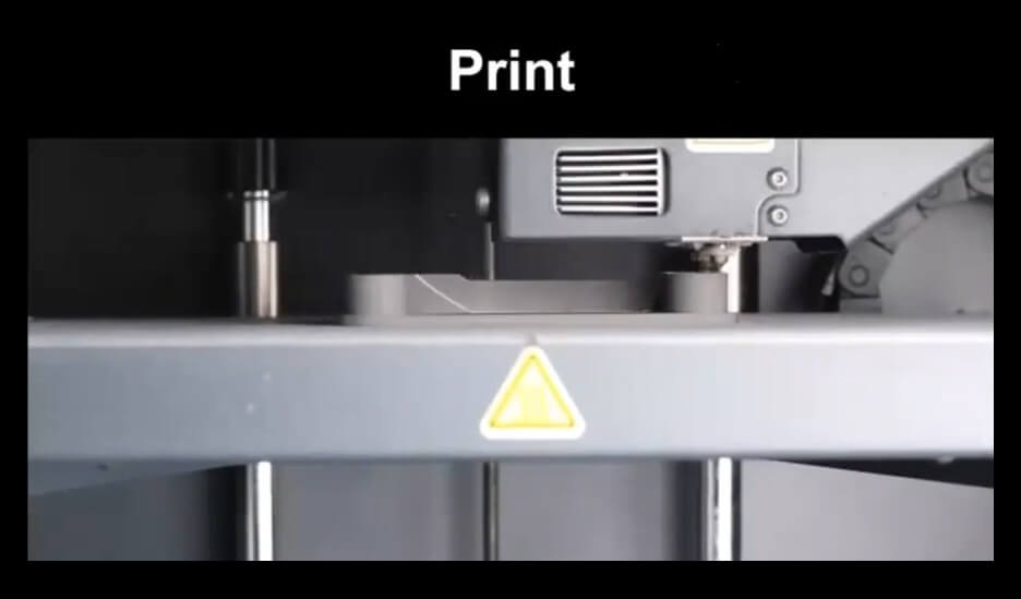
The part will be sent to the printer once the ‘Print’ button is clicked. As seen on the time-lapse below, 3 important details can be seen…
- It is producing the part that was selected
- It is producing a support structure – the structure is made from a native material the same as the part itself.
- The purpose of the white layer in between the support structure and the part is to make sure that during the post processing, the support structure doesn’t adhere to the part. This makes it possible to remove the supports by hand.
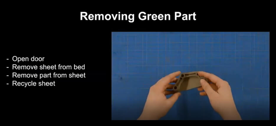
Printing - Removing the Green part
Removing the Green Part from the printer is very simple. Shown in the video below - the door is opened and the part is removed, which is on a print sheet. The sheet is a thin piece of recyclable plastic and the part can easily be peeled off.
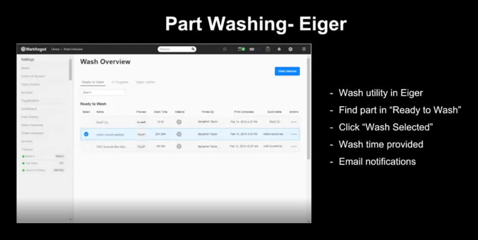
Washing: Eiger
The part is ready to go through the post processing system – which is managed through Eiger. Once printing is completed, the part will show under ready to wash. It has to be selected and the ‘Wash Selected’ button needs to be clicked. The wash is a solvent bath that breaks down the binder that is holding the metal powders in place. The wash time is calculated by Eiger and an email notification will automatically be sent once the wash is completed.
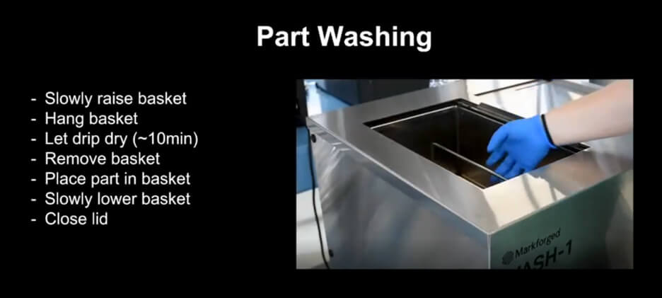
Washing: Wash Station
The wash lid must be opened and the basket raised slowly. Once it’s free from the solvent bath, the basket needs to be hung from the washer’s lid followed with 10 minutes of drip drying. The purposes of slowly raising the basket and drip drying are - both methods are there to preserve the solvent to keep it in the bath and prevent it from evaporating. Once the drip dry is completed, the basket can be completely removed from the washing station – easily allowing you to place the part in the basket.
The washing station is a batch process – allowing you to wash multiple parts simultaneously. Enough space must be left around the parts which will allow the solvent to have good contact – making it more effective in dissolving the binder. Once the basket is filled with parts, it can be lowered down into the washer followed with closing the lid.
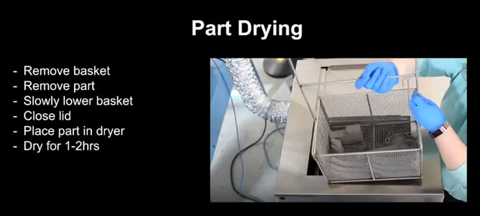
Drying
The parts are to be removed and dried once they are washed. The process is the same as the previous step – the basket raised slowly from the solvent bath followed with 10 minutes of drip drying. This allows the solvent to condense and return back to the solvent bath. Once the drip dry is completed – the basket can be placed on top of the wash and the parts can be removed. The basket can slowly be lowered back into the solvent bath if the parts need further washing. The drier is located on the other side of the washing station where the parts needs to be placed in. Once the lid is closed, the parts will need to sit in the dryer for about 1-2 hours. This will allow the solvent that’s on the parts to evaporate before sintering.

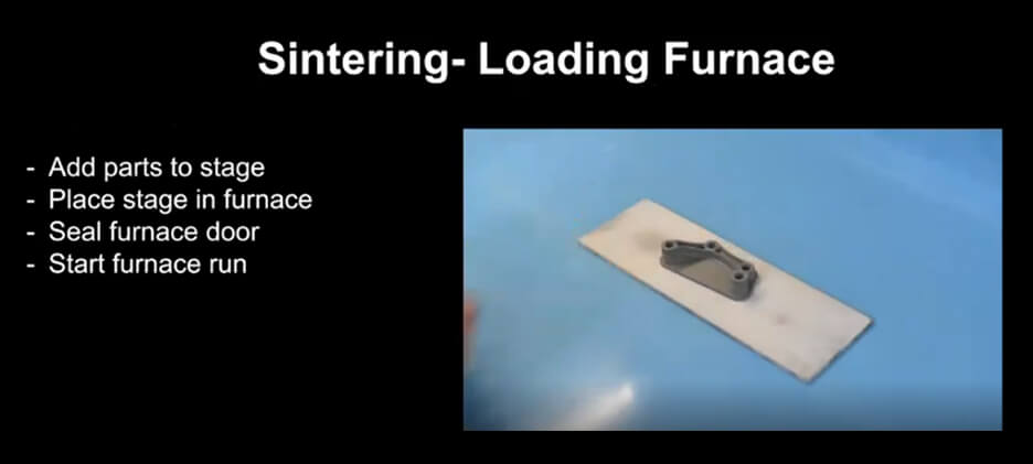
Sintering: Loading Furnace
Once the part/s are dry, they are placed onto a stage (a ceramic plate) and loaded into the sintering furnace – making sure it’s level and placed centrally. The furnace door needs to be sealed with 3 cap screws. An LCD screen is located at the front of the machine where the ‘Start Furnace’ option need to be selected. This option will notify Eiger that the parts are now sintering.
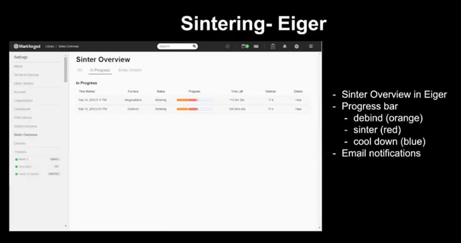
Sintering: Eiger
The sintering process is monitored by Eiger just like the washing process is. The most important detail to keep an eye on under ‘Sinter Overview’ are the progress bars. Each progress bar is divided into 3 parts – first is the orange portion which is the de-binding stage. This is when the furnace is heating the part and burning out what is left of the binder. The bar then progresses into the red portion which is the sinter profile. This increases the heat of the metal which allow the metal powders to densify together. Finally when the bar progresses into the blue portion – the part is cooled down. A notification email will then be received stating that the sinter process is now over and the parts can be removed.
Sintering: Unloading Furnace
To remove the parts from the furnace, the door must be unsealed by unscrewing the 3 Button Socket Head Cap Screws. Once the door is opened, the stage needs to be carefully slid out and removed from the oven. It is then placed on the bench top and the support structure can now be easily removed from the part (the ceramic layer has now turned to powder thus there is no thing keeping the two parts together).
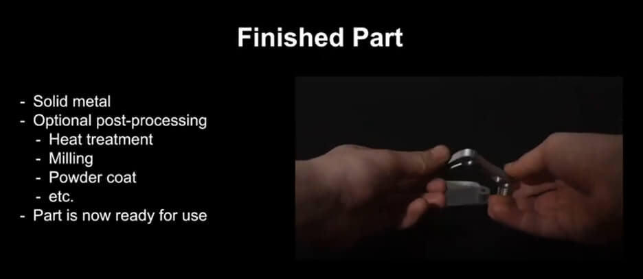
Finished Part
The binder has completely been removed by this stage. The solid metal part can now go receive any additional part post processing application that may be required. The part can now be heat treated, milled or powder coated just like any part made from that metal. It is now ready for use – it’s very exciting to see how a 3D model can be turned into a solid fully functional metal part using the Markforged Metal X system.