Creating Custom PLC Styles in AutoCAD Electrical
By Chami Ranaweera l Redstack Applications Engineer - Mechanical and Electrical
Understanding Parametric PLC Modules
PLC modules can be documented by inserting individual I/O points or by inserting the entire module as one symbol. PLC modules function like any other schematic components. They are AutoCAD blocks with attributes for tagging, connection points, catalog information, and other data.
The Insert PLC (Parametric) command automates the insertion of an entire PLC module. Each I/O point is a block inserted on a rung of an existing ladder. After an I/O point is inserted, the command searches down the ladder for the next rung and inserts the next I/O point, thereby adjusting the spacing between I/O points to meet the rung spacing. AutoCAD Electrical supplies hundreds of PLC modules if you install every manufacturer. But if you look at the drawings in the library folder you are not able to see many PLC modules. This is due to AutoCAD Electrical builds most of the PLC modules on-the-fly. It results, a block with attributes, but it is built from a small set of building blocks.
PLC Block Naming Convention
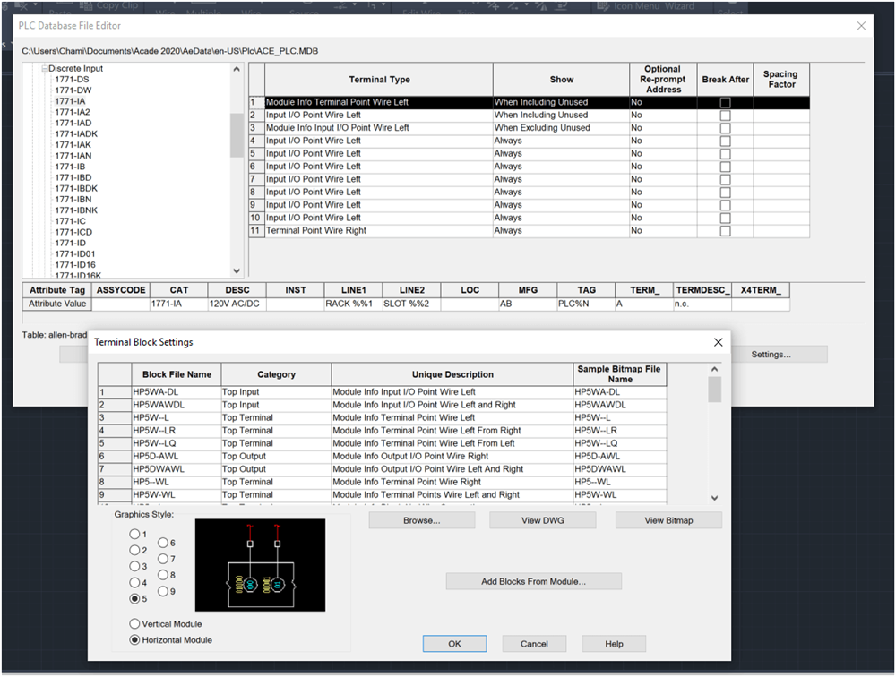
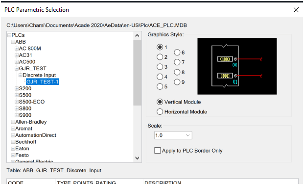
There are 5 out of the box PLC styles provided with AutoCAD Electrical, numbered 1 to 5. Number 6 to 9 is available for user defined PLC modules. There are about a dozen symbols associated with each style. They are in the NFPA, JIC, etc folders in the below locations depending on the standard you are using. They carry the file name "HP? *.dwg" where "?" is the style number.
Windows XP:
\Documents and Settings\All Users\Documents\\Autodesk\Acade{version}\libs\{library}\
Windows Vista, Windows 7:
\Users\Public\Documents\Autodesk\Acade{version}\libs\{library}\
Creating Custom PLC styles
It is better to start with a similar block when a new style is created. Make sure to copy the new blocks into your custom symbol library before modifying them. If you want to create an entirely new library rename all the numbers to 6, 7, 8, or 9 and then modify them as needed.
I am going to modify a few blocks as below. Each PLC module consists of around 20-30 blocks. Out of those blocks first, I modified HP5WA-DL as the top input. I also copied the wire connection point to the additional wires.
Below are all the blocks which belong to 1771-1A module.
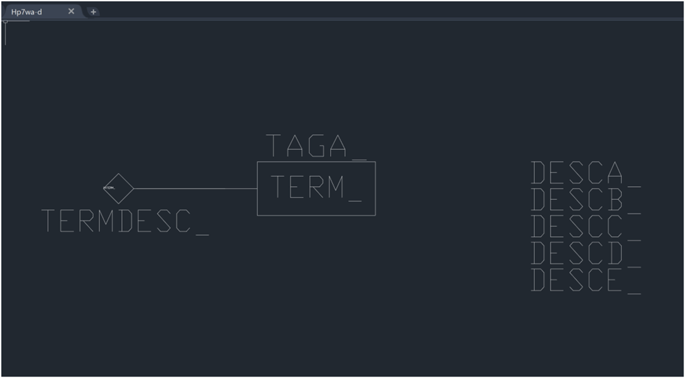
HP5WA-DL block is selected to modify.
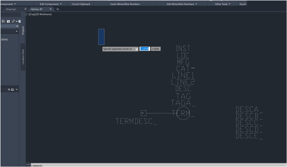
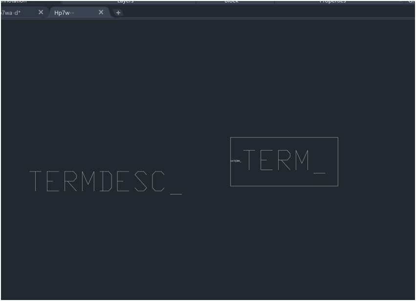
The modified block is saved as HP7WA-DL in the relevant library.
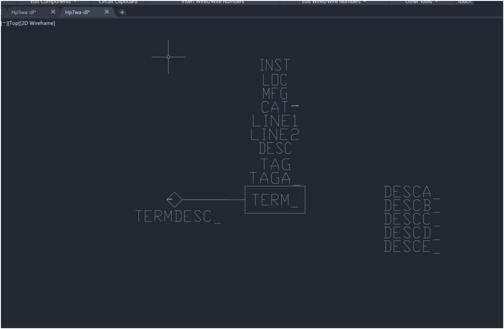
Then HP5WA-D, HP5W are modified and saved as below.
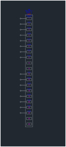
A new module has been created including 20 terminals as below.
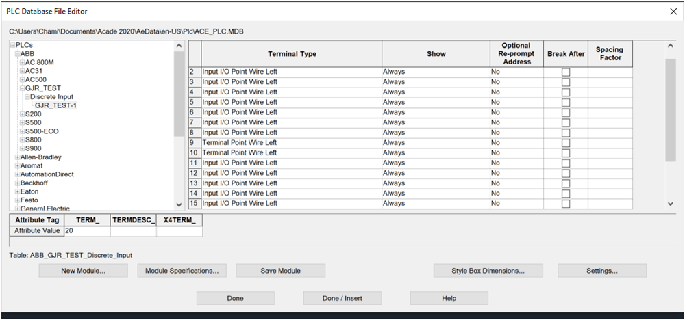
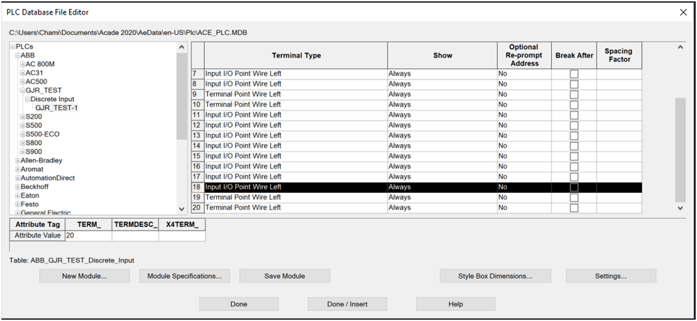
You can see the newly created block as below after inserting on to the drawing.
Creating PLC Style Image Files
There are two images files (.bmp) involve with parametric PLC modules and those use in Project/Drawing properties and Insert Parametric PLC Dialog box as below. These image files (.bmp) are used to display a graphical preview of the styles in various dialog boxes.
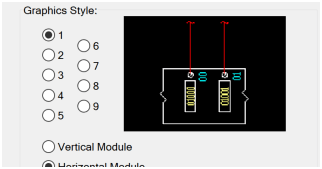
If you need to update the image files that go with the style they are listed here.
Windows XP: C:\Documents and Settings\{username}\My Documents\Acade {version}\AeData\Plc
Windows Vista, Windows 7:C:\Users\{username}\Documents\Acade {version}\AeData\Plc
The icon menu graphic that displays for the various PLC styles is bitmap files saved to \Program Files\Autodesk\Acade {version}\Acade\ This is where the Insert PLC and Drawing/Project Properties dialogs access them.
1. Create a style in AutoCAD.
2. Zoom in to the new PLC style.
3. Save the file as a bitmap using the following name definition:
For the Drawing Properties, dialog box: the graphic must have the name P_STYLExH.bmp or P_STYLExV.bmp where 'x' is the PLC style number (1-9) and H or V indicates the module orientation(horizontal or vertical).
For the Insert PLC dialog box: the file name must be STYLExH.bmp or STYLExV.bmp where x' is the PLC style number (1-9) and H or V indicates the module orientation (horizontal or vertical.
Summary
As a summary, first you must define the blocks associated with each terminal types which you are planning to utilise. All existing similar blocks must be opened, modified and saved as according to the correct library location with the accurate style number. Then you will have fully functional custom PLC style.
AutoCAD Electrical can be purchased as a part of the Architecture, Engineering & Construction Collection here: https://www.redstackshop.com.au/autodesk-architecture-engineering-construction-collection
We also offer AutoCAD Electrical training. Click here to learn more: https://www.redstackshop.com.au/training